© Brighteon.com All Rights Reserved. All content posted on this site is commentary or opinion and is protected under Free Speech. Brighteon is not responsible for comments and content uploaded by our users.
The Fortress Beehive is no regular beehive. The only things it has in
common with a standard Langstroth hive are the frames and associated wooden
boxes. Therefore, the assembly of the Fortress Beehive is different than a
Langstroth hive. The components from bottom up of the Fortress Beehive are as
follows: 1. The Foundation, which includes a Floor, Moat, Moat Cover, Pedestal
and Corner Guides. 2. The Vestibule, which includes (2) Take-off/Landing
Boards, (2) Awnings and between the 2 parts is the Entrance/Exit Slot - these
are duplicated on both sides, the Lower Screen that sits above the Pan that
catches debris, and holds either distilled water, or recycled "glass
bead" (used for sand-blasting), depending on the mode of operation: either
space heating, or varroa destructor mite thermo/hygro therapy treatment, in
both cases (2) 50-watt electric heaters are connected to the underside of the
pan and can be powered by solar panels or utility-provided 120-volts. 3. (2)
Deep and (2) Medium and (1) Feeder/Ventilation/Hive Volume Baffle hardwood
(chosen for its superior stability in outdoor conditions) boxes. The 'Combined
Function Box' (Feeder, Ventilation/Baffle) is placed vertically in the stack
just above the box intended for occupation by the bees (so, brood and honey
super boxes). This keeps the volume of the hive at an optimal amount so heat is
not wasted and the interior temperature of the brood box can be efficiently
maintained. The Combination Box is moved up in the stack when hive volume
expansion is desired so the bees don't swarm. This design allows for a fixed
number of boxes, therefore, a fixed length for the Lock Straps and Side
Shields. Any number of boxes/box sizes can be added to the (5) boxes if
desired, but taller Side Shields and longer Lock Straps can be purchased. 4.
The Side Shields and Corner "Bite" Guards fit around the box stack
and are held in place with a ratchet strap. 5. The Roof sits atop the upper
most box, with the Upper Screen in between. Alternately, the Fan Assembly Plate
can sit between the Roof and the uppermost box. When the Fan is being used for
solar-powered ventilation, the Upper Screen fits between the uppermost box and
the box directly below it, to prevent bees from entering the box being used as
a 'Ventilation Box' (in this application). 6. The 10-watt solar panel attaches
to the top of the Roof assembly and connects inside the Roof to the Fan Speed
Control USB cable. 7. (2) Thermometers (aka, temperature gauges) thread into
the 1/2" female ports located on the Vestibule and on the sides of the
Roof. This video shows the assembly of boxes, Side Shields, Corner Guards, Fan
assembly, Roof with solar panel and Fan assembly beneath it.
@RealBeeFortress https://www.beefortressusa.com
800-598-5949 #ReallySavingTheBees

The overlooked lifeline: How public libraries are a prepper’s best free resource

Gold Backs: A revolutionary return to sound money
Spring survival prep: Why preppers should embrace seasonal readiness

Decoding the Matrix: How global elites engineered chaos in the Middle East
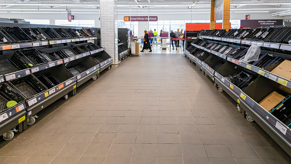
The panic cascade: 10 Crises that could empty store shelves overnight and how to secure your family’s food supply now